A digital angle gauge (digital protractor) is a measuring tool used to determine the angle or inclination of an object relative to a surface or a plane. This project is a prototype of such a digital protractor which provides precise digital readings using an accelerometer.
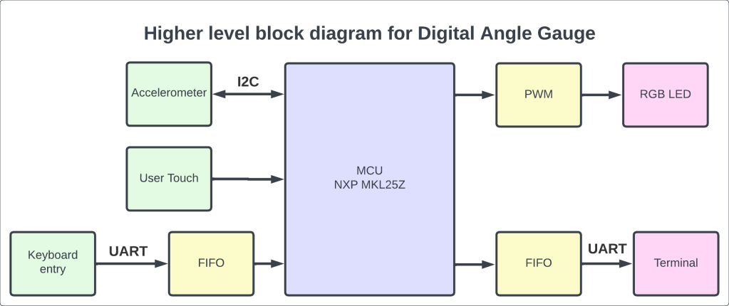
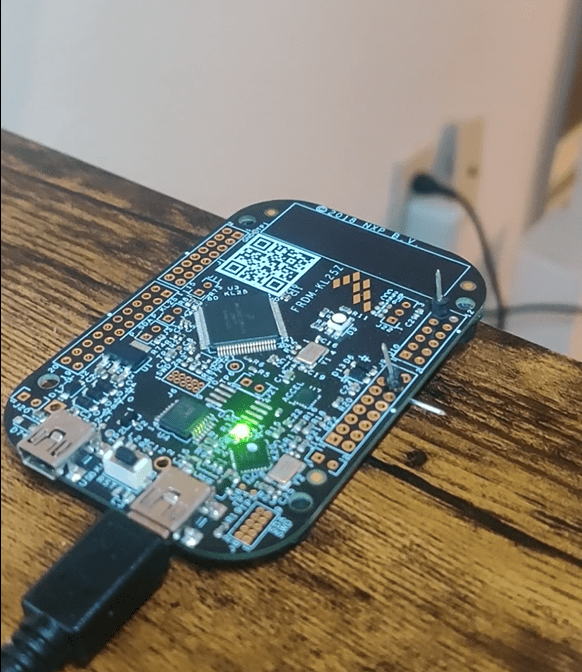
The prototype is developed using NXP Freedom KL25Z board, which uses KL25Z128VLK microcontroller unit which is a member of Kinetis L series of NXP MCU family. The development board comes with various peripherals such as accelerometer, touch sensor, RGB LED etc. The dev board also comes with support for various serial communication protocols like UART, I2C and SPI, USB etc. It also has ADC and DAC so that the MCU can be interfaced with a wide range of external analog and digital peripherals.
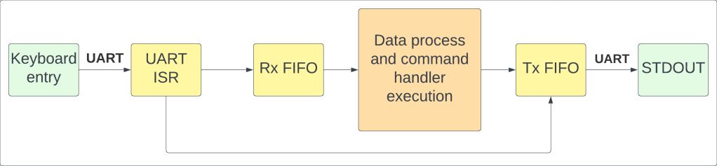
In this application, we create a command terminal, which can process a predefined set of commands available to the user to generate desired output. The command terminal is created using UART interrupt as a communication medium between the user and the MCU. Using UART, we receive the data in interrupt mode, while we transmit the data in polling mode. The command terminal with UART works as follows:
- The user types a command on the terminal.
- As soon as a character is received, UART interrupts the MCU, and UART interrupt service routine (ISR) is called.
- In the ISR, we enqueue the received character in the FIFO to be then processed by the MCU. The character received just now is also printed back to the terminal, so that user can see the character entered.
- As soon as the user hits the enter key, the FIFO is sent to command processing function, which then determines whether the command entered is valid and executes the corresponding command handler.
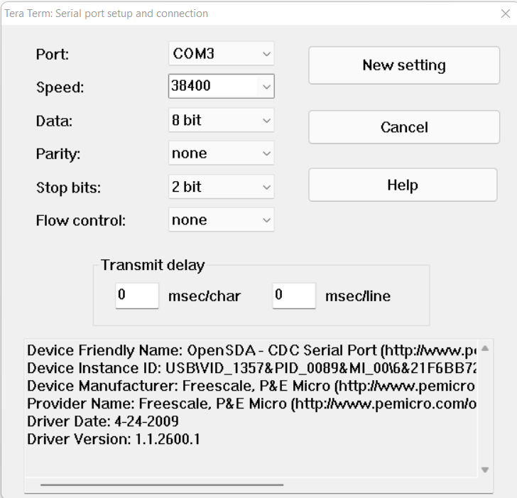
For the ease of understanding, and to avoid using tedious UART transmit/receive functions, we simply redirect the C library’s printf() function to our custom FIFOs, so that the data we receive and transmit will be easily accessible to us. We use 2 FIFO queues, one that receives data from the user, and then we use that data to process the command and execute the command handler; and other FIFO is used to transmit data, which is the output generated from the command handler to be sent out to user terminal, in this case, stdout. Following are the parameters used to configure the UART communication:
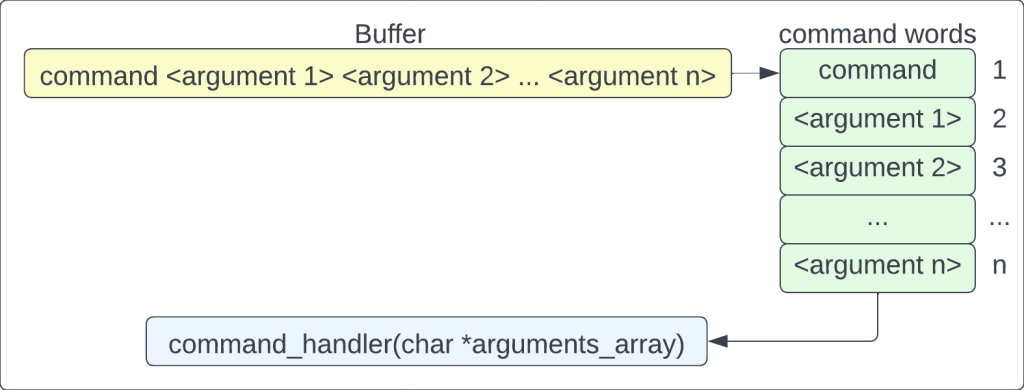
In the command processing part, we break down the input buffer (essentially a string with a command and all the arguments, if any) into an array of strings, or array of words, so that we can easily distinguish between the command and the arguments provided for the command. Traditionally in Linux and other major operating systems, command is always the first word entered, followed by arguments or flags for arguments. Similarly, after breaking down the input string into an array of words, we look at the first word to identify the command. The first word is compared against a lookup table for a match. If the command entered matches an entry in the lookup table, it is a valid command, and the command handler is called along with all its arguments. If there is no match, an error message is printed to the terminal, and user is asked to enter a valid command.
The commands available to user are:
- Author: Prints the name of the author of the application code
- Help: Prints a help message for the user to understand the entire application and available commands
- Brightness: Lets you adjust the brightness of the RGB indicator LED
- Angle: Helps you achieve the desired angle for the digital protractor
- Color: Lets you change the color of indicator LED for a particular command
- Touch: Lets you adjust the brightness of the LED using the touchpad. First, if the brightness is greater than 0, a tap will gradually decrease the brightness by 10%. Once, the brightness is 0 (LED OFF), tap will increase the brightness gradually by 10%. This goes so on and so forth till we perform a hard tap on the tsi module which is the exit condition of the loop.
- Calibrate: To calibrate the accelerometer to a certain value. For example, if we calibrate the accelerometer to at 20 deg, then 20 degrees become a reference axis for the accelerometer and then all the readings will be taken relative to 20 degrees.
Digital protractor is just one of the functionalities of this application. The protractor uses an accelerometer which gives measurement across X, Y & Z axes, and then the relative position of the sensor is used to determine the angle made by the accelerometer with respect to the reference plane. The communication between the MCU and accelerometer takes place using I2C.
RGB LED functionality is implemented to act as an indicator for user to know which command is being executed or which command was executed last. Each command has been allocated a color by default:
| Command | Color | Hex Value |
| Author | Cyan | 0x00FFFF |
| Help | Neon | 0x70FF07 |
| Brightness | Sky Blue | 0x0770FF |
| Angle | Yellow | 0xFFFF00 |
| Color | Magenta | 0xFF00FF |
| Touch | Blue | 0x0000FF |
| Calibrate | Green | 0x00FF00 |
| Invalid Command | Red | 0xFF0000 |
Other available colors are:
| Color | Hex Value |
| Pink | 0xFF70FF |
| White | 0xFFFFFF |
The user can change the color assigned to the command at his discretion. Use ‘color’ command for the same.
The user can set angle using the ‘angle’ command. See help command for more information. Once the angle is set, then the LED will start blinking with Yellow color (unless the user chooses to change the color). Once the desired angle is reached, the LED will start glowing solid yellow color (unless user changes this color assignment).
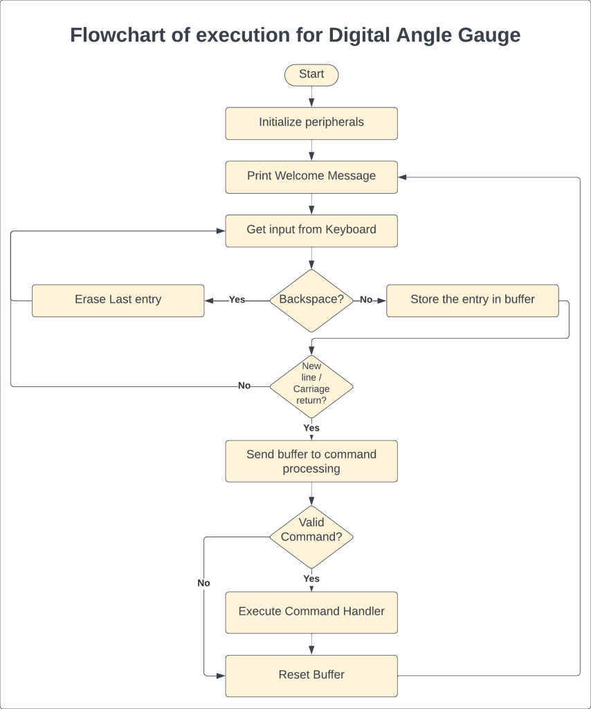
Here is the overall flowchart of the prototype:
To control the color displayed on RGB LED, we use three different timers to generate three different pulse width modulated (PWM) signals, one for each color, Red, Green and Blue. By adjusting the duty cycle of each color PWM, we can display a wide variety of colors on the RGB LED. Refer to this link by Rapid Tables for various 24-bit color combinations for RGB color palette. It is trivially easy to add colors to this application, one has to simply add the color name in the enumerated list of colors, and then add the configuration of color in the initialization function, and boom, you have a new indicator LED color for your application!
The source code for this application is open, you can download the code and modify it and play with it!
Source code: https://github.com/tanmay-mk/Digital-Angle-Gauge/tree/main
Demo: Link
A large part of this source code was written as a part of my assignments during my graduate studies at University of Colorado Boulder. This source code takes reference from various sources, and I would like to quote a few:
- Alexander G. Dean’s repository: https://github.com/alexander-g-dean/ESF/tree/master/NXP
- Howdy Pierce: https://github.com/howdypierce
- Geeks for Geeks
- Stack Overflow
- Stack Exchange
All the references have been accredited in the respective source and header files.
Software tools used:
- MCUXpresso by NXP
- TeraTerm for serial terminal
- PuTTY serial terminal
- KL25Z Software Development Kit (SDK)
Hardware tools used:
- FRDM-KL25Z development board

Leave a comment