Introduction
In the modern era we are moving towards unmanned vehicles at a rapid speed. Self-driving cars have become one of the most exciting technologies over the past 3 years. These cars are automated and require less or no human intervention. Society of Automotive Engineers (SAE) have classified this automation into 6 levels. These are – Levels of driving automation
- Level 0 – no automation
- Level 1 – hands on / shared control
- Level 2 – hands off
- Level 3 – eyes off
- Level 4 – mind off
- Level 5 – steering wheel optional
As of March 2022, very few vehicles are operating at level 3 and above. They remain a marginal portion of the market. These self-driving cars have many features and technologies used in them. Amongst many, one of the key features is sign detection. There are so many different signs on roadways like stop signs, traffic lights (red, green, yellow), pedestrian crossing signs, speed limits etc. It is very important that an autonomous car captures these signs, recognizes it, and takes appropriate action in the required amount of time. Basically, this is a case of a real time embedded system where sign detection, identification, and the action, each need to be completed before a certain deadline to prevent accidents and cause harm to other vehicles.
In this project, we designed and developed such a real time system which emulates a self-driving car, captures, and detects traffic signals and performs the necessary action within a certain deadline. In real world applications, we cannot assume ideal cases for any system. Especially if the system is hard real-time and failure to meet the deadlines can lead to fatal accidents. This is true for the braking of any vehicle as well. No vehicle will come to a stop at the exact instant the brake is pressed. The time it takes for a vehicle to stop after applying brakes depends on multiple factors like quality of brakes, weight of the vehicle, speed at which the vehicle was traveling and friction between the tires and the road. The distance the vehicle travels in this time is called the braking distance. We have taken this into account while designing our system. The exact numbers and calculation have been explained later. Our system also deals with obstacles using an ultrasonic sensor for distance measurement.
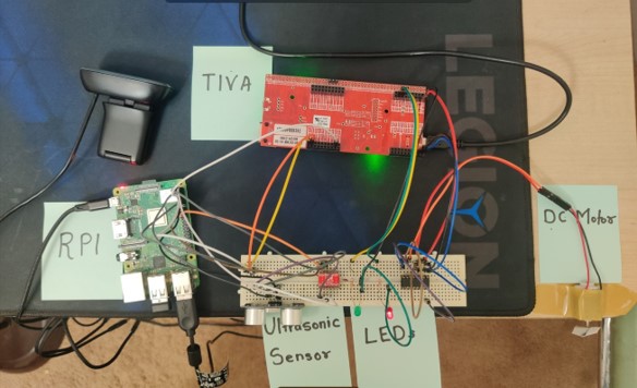
Our system will consist of a USB camera (C270) which will be connected to the Raspberry Pi. The Raspberry Pi will communicate with the TIVA board over UART. There will be a DC motor and multiple LEDs connected to the TIVA board to demonstrate actuation. The motor can be considered to be emulating a car wheel which needs to stop or change speed depending on the sign detected. The other input to the system is through an ultrasonic sensor input which is used for detecting obstacles for emergency braking. The input of an ultrasonic sensor is going to override the traffic light value any time an object is encountered below the threshold of 35cm. The camera will keep capturing images at a rate of 2.22 Hz. These images will be processed by an algorithm which will identify the signal. The detected signal data will be transmitted over UART to the TIVA controller which will then take the required action of either stopping the motor or changing its speed. The TIVA controller will be running FreeRTOS since it is highly accurate and can be used to meet hard real-time deadlines.
Functional Requirements
Speed control and braking mechanism is a critical feature of self-driving cars. Here, it is very important that all aforementioned tasks (light-detection, identification, and actuation) have to be completed within a specific deadline. If the system fails to do so, it will result in a crash, maybe a fatal one. Therefore, this system is considered as a ‘Hard Real-Time System’.
The system should be capable of:
A. On Raspberry Pi Board:
- Capturing the frame using the camera at a required rate.
- The captured image should be processed within a certain deadline, and the light-detection algorithm should be able to accurately identify the type of light (Red, Yellow or Green).
- The ultrasonic distance sensor should record the correct distance and send accurate data to the microcontroller (stretch goal implemented).
- Depending on the type of light (or obstacle) detected, the Raspberry Pi should send a message to the TIVA board over UART.
- Wait for acknowledgement from TIVA Board.
- Log the WCET and Average ET for all services. B. On TIVA Board:
- The TIVA board should receive data from Raspberry Pi over UART, and send an acknowledgement back.
- Based on the value received from Raspberry Pi, the TIVA board should adjust the duty cycle of PWM for motor control.
- The adjusted PWM should be directed towards the DC motor to simulate speed control.
- Based on the value received from UART, the TIVA board should actuate the corresponding LED.
As mentioned earlier, speed control is a mission-critical feature and hence all services should be completed within a certain deadline. Furthermore, the image processing algorithm should be designed meticulously to specifically identify traffic lights and should not be limited to color detection. The problem with just color detection is that the image processing algorithm may produce false results based on other elements in the surroundings. For example, we don’t want speed control to occur when the camera sees a different object (probably a car of Red or Yellow color). Catering to such false data will result in fatal accidents on the road. Hence, the algorithm should only identify a Red/Yellow/Green light when there is a definitive circle of the said color.
Frame capture, processing, light detection, data transmission and reception, and actuation; all these services should complete in a very specific deadline so that there is enough time (and distance) left for the car to gradually come to a full stop.
Functional Design Overview & Diagrams

Our system uses two boards, namely Raspberry Pi 3B+ and TIVA TM4C1294GXL. All sensing part (frame capture and distance measurement) will occur on Raspberry Pi and all actuation (motor control and LED indications) will occur on TIVA board. For sensors, we are using a Logitech C270 camera and an ultrasonic sensor. These sensors will provide the data ‘sensed’ from the real world to the Raspberry Pi. The Raspberry Pi will process this data and create a small data packet which will be transferred to the TIVA board over UART communication. Once the TIVA board receives the message, it will generate a PWM signal corresponding to the data received from Raspberry Pi. This PWM signal will then be directed towards a DC motor to simulate speed control. Furthermore, the TIVA board will also actuate a couple of LEDs to indicate the status of the vehicle, whether it is running or not. The Red LED will glow if the car is stationary, and the Green LED will glow if the car is moving.
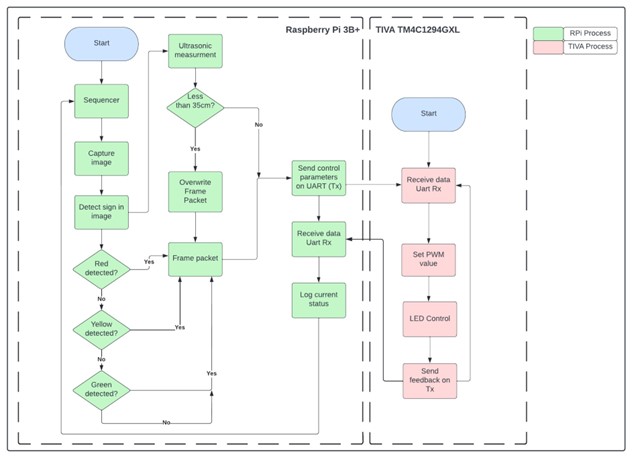
Software Block Diagram depicts the software flow diagram for the proposed system. For the raspberry pi, we are using pthreads to implement a multithreading application and a sequencer which will schedule all the tasks.
First, the software will capture a frame at 2.22 Hz and send that image for processing to the traffic light detection algorithm. If the processing algorithm detects a traffic light, it will immediately exit the processing loop and store the information about traffic light in a data packet.
After that, we take the distance measurement from the ultrasonic sensor. If any obstacle is detected, then it will overwrite the data packet created by the image processing algorithm as a hint to the actuating microcontroller to perform immediate braking. If there is no obstacle detected, the Raspberry Pi will send the traffic light data over to TIVA using UART communication. Once the TIVA board receives the message, it will take corresponding steps to perform actuation. Once the actuation begins, the TIVA board will send an acknowledgement back to the Raspberry Pi board that the actuation has been successfully achieved. After reception of the acknowledgement message, the Raspberry Pi will log all the timings for services. This process repeats indefinitely.
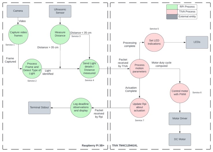
Data Flow Diagram explains how data flows in our system. Input data is obtained from the 2 sensors – camera and ultrasonic sensor. The frame captured is passed to an image processing algorithm where the traffic light is detected. This algorithm first detects a circle and then detects the color. This data along with ultrasonic data is transferred over UART to the TIVA board. The reason we are doing this is that in a real car, there are multiple microcontrollers with multiple sensors interfaced. These controllers communicate with each other and pass data using the CAN protocol. To simulate such a behavior we have implemented this communication. To simplify stuff, we have used the UART protocol. On the TIVA board, we are controlling the speed of the motor and color of the LEDs based on the data received from the RPI. Once the actuation is initiated the TIVA board sends a feedback message back to the RPI. Based on this message RPI does the time calculation.
Real Time Requirements
For a real life system like ours, we needed practical data to determine our deadlines. According to the National Safety Council, a lightweight passenger car traveling at 55mph can come to a halt in about 200 feet. For prototyping purposes, we scaled these numbers by a factor of 250 which means that a car going at a speed of 9.83 cm/sec requires 24 cms to stop. The distance of our camera from the signal is 35cm. At the above speed the car would require 3.55 seconds to cover this distance. Out of this time, 2.479 seconds will be spent in braking. Hence we have 1.079 seconds left for our services to execute.
Real-Time Services – We have a total of 7 services each of which are explained below.
Service 1: Frame Capture
This service will capture the frames from the camera using cv::VideoCapture.read() function. This function returns a numeric multidimensional array of the data that is extracted from the frame captured and stores it in a cv::Mat variable. We are also using a flag to check whether the frame was acquired successfully. If the frame acquisition fails, we will halt the system by entering an infinite loop.
Service 2: Processing image and traffic-light detection
This service will perform a color detection and contour detection to check whether a light has been recognized or not. We are capturing the images in BGR format, and converting them into HSV format. In OpenCV, object and color detection is usually done by converting the format of image to HSV. Once the mask of HSV format is created for the captured frame, we then perform contour detection to identify circles present in the image. As soon as the algorithm detects a light, we exit the processing loop and create a data packet which stores the information about the type of light identified. If the algorithm does not detect any traffic light, then it will store a zero value in the data packet.
Service 3: Ultrasonic Distance Measurement
The service executing the ultrasonic sensor functionality implements the ultrasonic sensor driver code for reading distance values calculated in cm scale. The driver code is implemented in such a way that a 10us pulse train is sent from the output trigger pin. These pulses are received on the input echo pin after a certain time and based upon this delay and assuming the speed of sound as 34300cm/sec we calculate the distance. The value of distance is then provided inside our ultrasonic distance measurement service thread using get_distance() API which we have implemented. If the return value of this function is less than or equal to 35cm, the stop signal packet is sent to Tiva overriding the data from camera, as the motor should be stopped irrespective of the traffic light status in case an obstacle is encountered.
Service 4: UART communication RPI
This service is dedicated for transferring data from the Raspberry Pi to the TIVA board. The data to be transferred is obtained from Service 1 and Service 2. We have not used libraries on the RPI end. Since we know that in a linux based environment all devices are treated as files. Thus we use this mechanism coupled with system calls like open, write and read on the /dev/ttyS0 file to transfer the data. On the TIVA end this data is received along with an interrupt generation. Within this interrupt we write the data to the message queue.
Service 5: Speed control of motors
According to the value received through UART from the raspberry pi, the speed of the motor is controlled. For green light a PWM value of 60% is applied to the motor, for yellow light 40% is applied to slow it down and for red light and <30cm udm value 0% is applied for immediate braking.
Service 6: LED color control
Depending on the data obtained from the RPI, we change the color of the LED. This is done by simply sending a GPIO signal to the pin.
Service 7: UART communication TIVA
Once the actuation is initiated on the TIVA end, it sends a success message back to the RPI over UART. This service handles this communication.
Deadline and WCET
If we consider 1 second as the deadline for our services, there is a chance that the system might miss its deadline. It is possible that while the image is being processed, there is another frame available which has a different input compared to the previous one. In this case the processing of this frame will be delayed until after all the services have been completed. This delay could be significant since the image processing service is our heaviest service and takes a lot of time compared to others.
Hence we decided that we should be getting at least 2 sets of inputs (frame and distance) during the 1 second system requirement. Thus we chose a deadline of 450ms for our services. After running the services, we obtained the following worst case execution times
| Service | Name | CPU | WCET Ci | Deadline Di (ms) | Period Ti (ms) |
| S1 | Image capture | RPI | 18 ms | 450 | 450 |
| S2 | Sign detection | RPI | 181 ms | 450 | 450 |
| S3 | Distance measurement | RPI | 112 ms | 450 | 450 |
| S4 | UART communication | RPI | 10 ms | 450 | 450 |
| S5 | Motor Control | TIVA | 7 us | 450 | 450 |
| S6 | LED Control | TIVA | 9 us | 450 | 450 |
| S7 | UART communication | TIVA | 7 us | 450 | 450 |
Real-Time Analysis
We performed Cheddar Analysis for both RPI and TIVA.
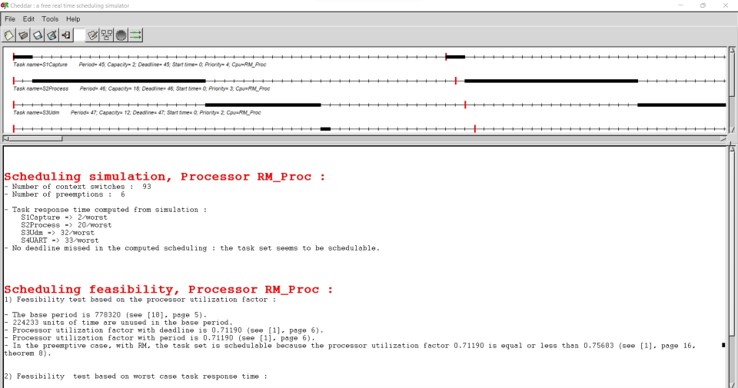
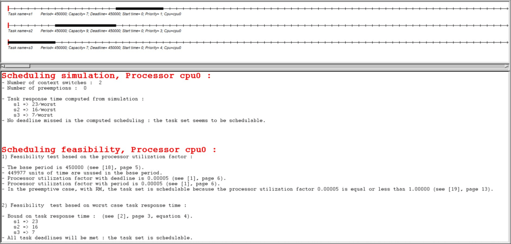
In the case of RPI we observed that for the given service execution times and periods, the CPU utilization comes out to be 0.71 or 71%. This value is below 75.6% RM LUB condition and hence satisfies the RM LUB. The schedulability tests also prove that the service set is schedulable.
In the case of Tiva, the service set is also feasible and much below the RM LUB condition at 0.005%. Such a high utility is proven with the timing diagram which displays a lot of slack time in between the various cycles of task scheduling. The task set is also shown to be schedulable as would be the case due to very low CPU utilization.

Scheduling point completion point test results:
For the above screenshots of cheddar simulations we can see that for both the case of Tiva and Rpi we got the service sets as schedulable for completion point and scheduling point tests conducted on the cheddar. The utilization is also below the RM LUB condition hence the system satisfies the necessary and sufficient condition.
Safety margin analysis:
For the case of services on Raspberry pi, the CPU utilization comes at 71%, hence the utilization is under RM LUB condition for 4 services and also has sufficient margin of around 29%. For the various services on Rpi, the WCET is also below the expected values for example 18ms for image capture where we assumed the WCET to be 50ms, hence there is margin available for this service and also other services. For Tiva, the service utilization is only around 0.005% hence more than sufficient margin is available to add more services or even if there is any jitter in the WCET value of the services on Tiva. The reason for such a high margin on Tiva is that the period for services is assumed to be 450ms which is of the system and is much higher than the Ci value of services in the 6-9 microsecond range.
Proof of Concept with example output & Tests completed
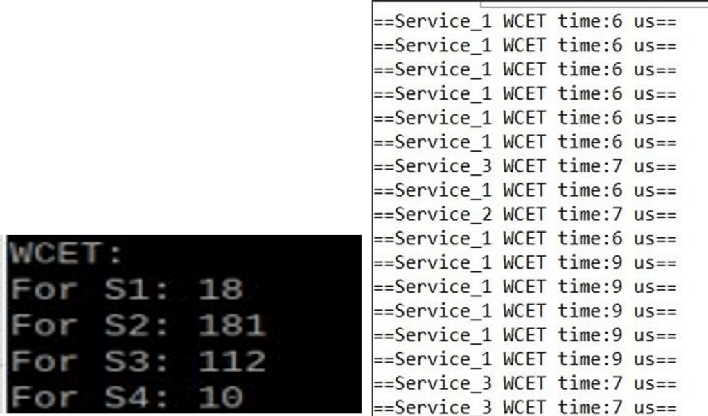
The above snapshot shows the WCET values obtained for both the boards each running their respective services for a duration of upto 5 minutes. For Tiva, we can see multiple prints of WCET as the corresponding line is printed for a service only when the new WCET is greater than the last WCET. Thus we see multiple print outputs for service 1 and 3 as their WCETs are changing with time and not for service 2.
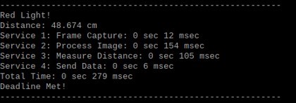
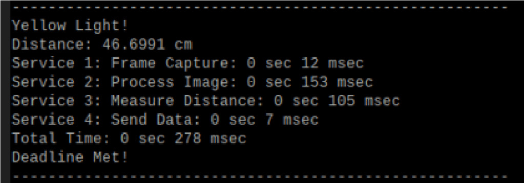
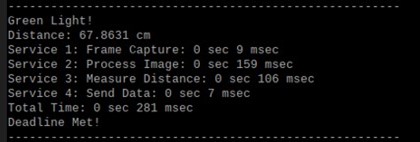
The above 3 screenshots show the valid traffic lights captured case and their corresponding logging threads. The execution times for each task are almost equal for all the three cases. The deadline met criteria is shown based on the weather acknowledgement received from the raspberry pi within the deadline of 450ms. The above figures basically show the timestamp tracing results.
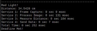
The above snapshot shows the test case 4 for UDM input, when the distance is less than 35 cm. Since the obstacle is treated as a red light condition, red light detected is shown. The response received for this input is higher than camera service.
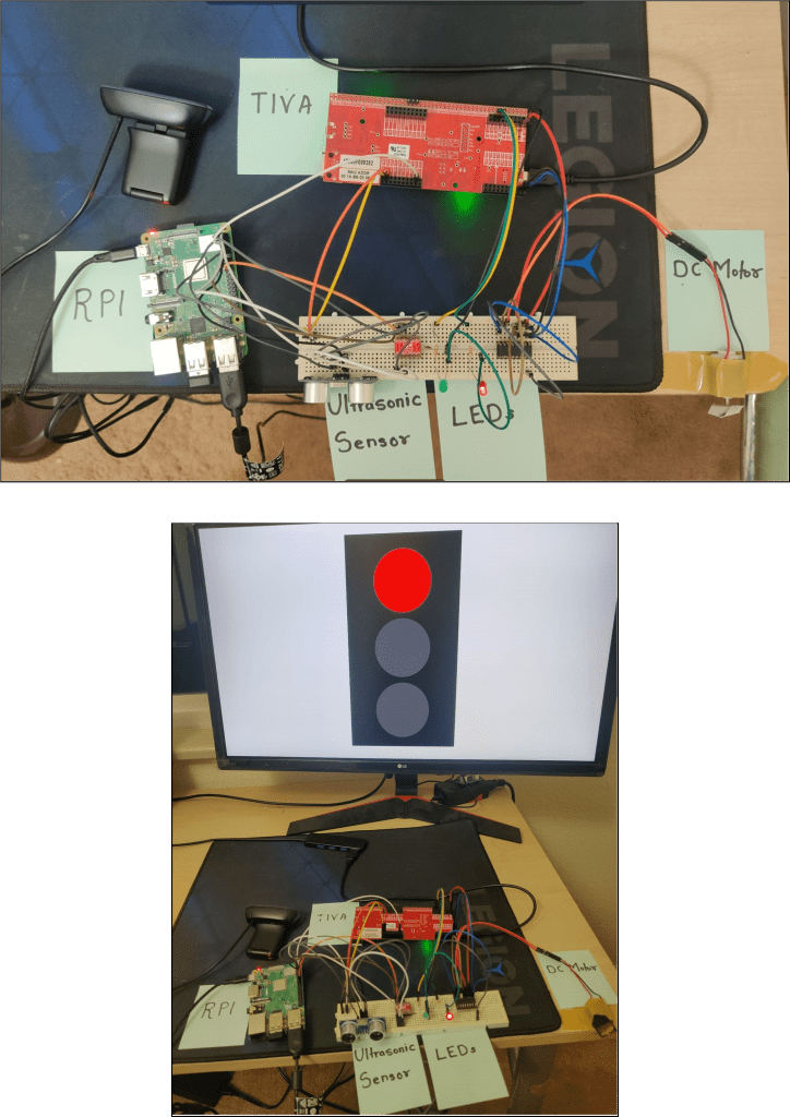
Hardware Setup
The above snapshots display our project setup consisting of all the components present in the hardware block diagram along with a monitor to display the different traffic lights for the camera to demonstrate project working. As it can be seen in the video the complete system performed according to expectations.
Conclusion:
Speed control for self-driving cars is a mission critical system and implementing such a hard real time system was a great opportunity to understand the dynamics of autonomous vehicles and the factors that are considered while designing the system. In our prototype, we successfully implemented a hard real time system utilizing FreeRTOS and Embedded Linux. For image processing purposes, we developed an algorithm which will detect contours on a processed frame which will be masked using Hue, Saturation and Vignette values. In the case of the ultrasonic sensor, the observed response time was much lesser than what we expected initially. Hence, simulating immediate braking was successfully implemented. For the TIVA board, we used FreeRTOS as an operating system and scheduled all the actuation tasks successfully. The dependency of TIVA board’s actuation based on input from Raspberry Pi board was a little bit difficult to achieve due to raspberry pi’s uart driver library functionality issues.
Overall, all deadlines were met for the defined services. After performing feasibility analysis, Rate Monotonic Least Upper Bound for Raspberry Pi would be 0.75 and actual CPU utilization is 0.71. In the case of TIVA, the RM LUB would be 0.77, and the actual CPU utilization is 0.00005. Thus, the developed prototype is feasible using rate monotonic policy. We also performed Cheddar analysis to ensure our calculations matched the simulated output.
Key Learnings:
- Multithreaded application development using Pthreads and FreeRTOS.
- Synchronization of multiple services using semaphores and message queues.
- Basics of image processing for object, color and contour detection.
Challenges:
- High image processing time.
- UART communication between RPI and TIVA.
Future Scope:
- Detection of traffic signals including speed limits and different signs.
- Use of dedicated GPU for lower capture latency.
- Using an improved image processing model utilizing machine learning to improve accuracy in different environments.
The source code for this application is open and you can download this project and use it.
Source code: Link
Demo: Link
References:
- Real-Time Traffic Light Signal Recognition System for a Self-driving Car Link
- Image contour detection algorithm Link
- Traffic Light Detection and Recognition for Autonomous Vehicles Link.
- National safety council guidelines for driving Link.
This project was a group effort during our Spring 2022 semester as a part of Real-Time Embedded Systems course.
Other group members:
- Sanish Sanjay Kharade – Sanish.Kharade@Colorado.Edu
- Vishal Raj – Vishal.Raj@Colorado.Edu

Leave a comment